IIC通信协议

基本功能

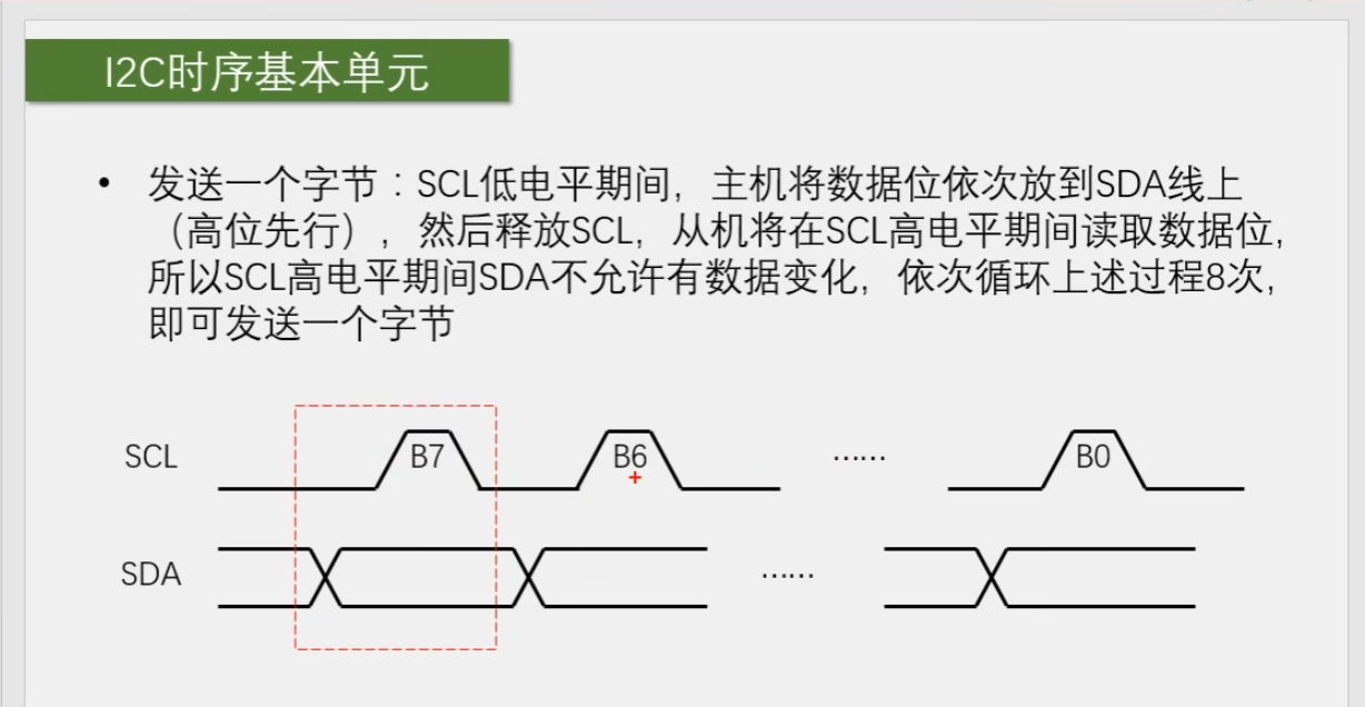
  • 同步时序的稳定性比异步时序更高

  • 半双工

  • SCL、SDA两根通信线

  • 支持总线挂载(一主多从,多主多从)

硬件电路

  • 所有I2C设备的SCL连接在一起,SDA连接在一起
  • 设备的SCL和SDA均要配置成开漏输出模式(防止形成短路电流,SDA要么被上拉,要么输出低电平),会有“线与”的现象。在多主机的模式下,可以利用线与的特性,实现总线仲裁和时钟同步。
  • SCL和SDA各添加一个上拉电阻,阻值一般为4.7KΩ左右

PS:IIC时序是高位先行,串口是低位先行


PS:主机接收时,需要释放SDA,即输入模式


PS:从机的地址可以通过电路改变
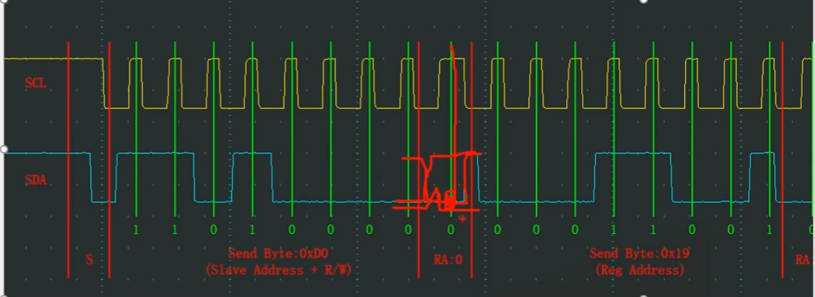

红线处,此时需要从机应答,这里如果但看主机的SDA,应该会释放SDA,即高电平,由于从机要发送应答,根据线与的特性,这里拉低了SDA,所以最后SDA呈现图中所示。
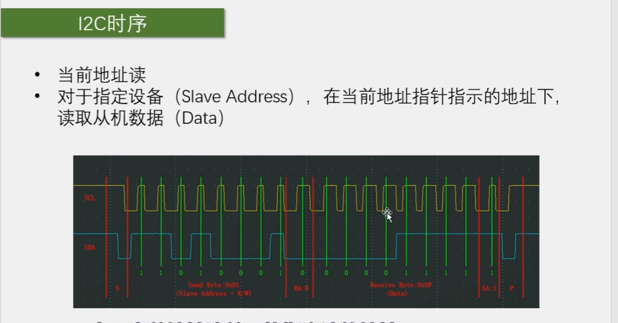

IIC通信的设备中会有单独一个字节空间存储地址指针,当给IIC设备指定地址写时,地址指针会加一,这时如果使用当前地址读,就是读取指针地址指向的内存。此时序较为少用、
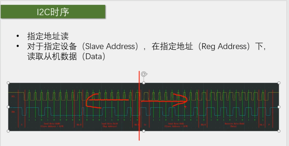

指定地址读的实现原理:先调用指定地址写,但是不写数据。再次调用当前地址读,这样复合的时序就能完成指定地址读的功能了

MPU6050

姿态角(欧拉角)

飞机相对于初始三个轴的夹角:

  • 俯仰角:Pitch
  • 滚转:Roll
  • 偏航:Yaw

要想获得稳定的欧拉角,就需要进行数据融合,进一步得到姿态角。

常见的数据融合算法:

  • 互补滤波
  • 卡尔曼滤波

ps:惯性导航领域里,姿态解算

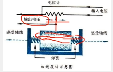
加速度计结构

F=ma(测力计)
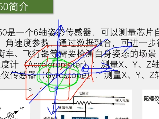
加速度计测得的是静态加速度,只能在物体静止的时候使用

陀螺仪传感器
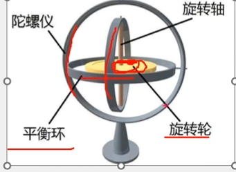
测得的是角速度,要想得到角度,可以进行求积分

陀螺仪具有动态稳定性,不具有静态稳定性

对两种传感器进行互补滤波,就可以得到稳定的姿态角了

MPU6050的参数
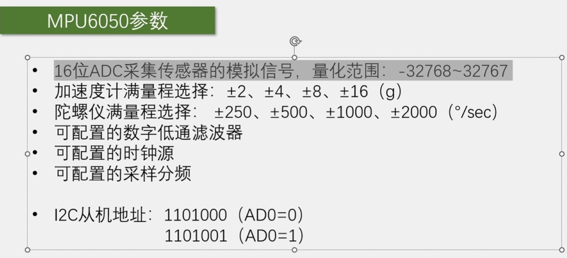
eg: mpu6050的从机地址:0x68 ,IIC时序中发送的第一个字节,高七位为从机地址,第八位为读写位。有时候把0XD0当作MPU6050的地址

硬件结构
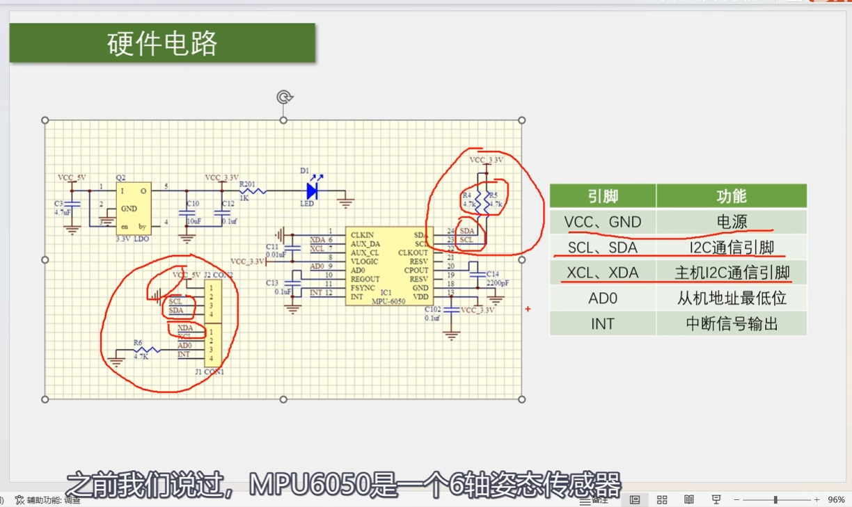
六轴传感器的缺点:没有稳定的参考方向

XCL,XDA:挂载磁力计,气压计

INT引脚:可以配置MPU6050内部一些事件,产生电平跳变

PS:MPU6050内部包含DMP单元:进行姿态融合和数据结算

包含稳压电路

传感器内部含有自测单元

使能自测->读取数据1->失能自测->读取数据2,两个数据相减,得到的数据称作自测响应,自测响应如果在规定的范围内,说明芯片性能没问题。


电荷泵
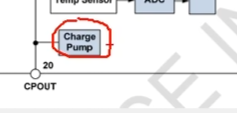
是一种升压电路

原理:电源和电容串并联的切换(充电->串联->相当于电压升高(放电)->快速切换到并联->充电->循环)+ 电容滤波 = 平稳升压
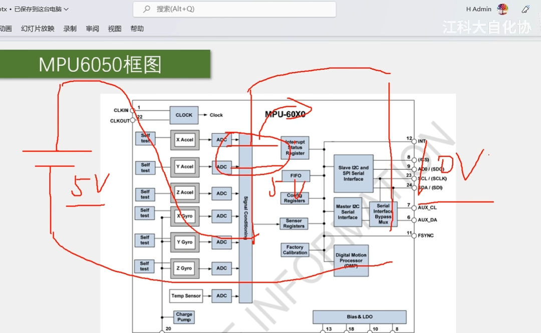

DMP(数字运动处理器)
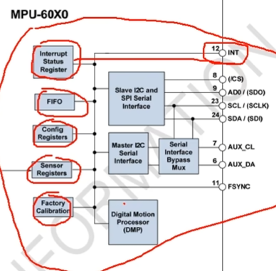
配合MPU6050官方的DMP库,进行姿态解算。

引脚说明

FSYNC:帧同步

通信接口:用于和STM32通信

xxxxxxxxxx python script_name.py --train_data_dir “path/to/train_data” --test_data_dir “path/to/test_data” --img_height 128 --img_width 128 --batch_size 64 --epochs 15python

​ 可以拓展连接磁力计


软件IIC读写MPU6050

1
2
3
4
5
6
7
8
9
10
11
12
13
14
15
16
17
18
19
20
21
22
#include <stm32f10x.h> 			//Device header
#include <Delay.h>
#include <OLED.h>
#include <MyIIC.h>

int main(void)
{
OLED_Init();

/*主机寻址MPU6050*/
MyIIC_Init();
MyIIC_Start();
MyIIC_SendByte(0xD0);//1101 000 0 前七位为MPU6050的从机地址
uint8_t Ack = MyIIC_ReceiveAck();
MyIIC_Stop();

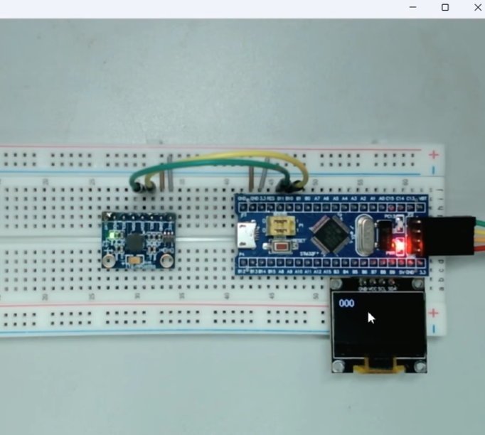
OLED_ShowNum(1,1,Ack,3);
while(1)
{

}
}

修改MPU6050地址

可见,寻址无应答


读取MPU6050 ID号

1
2
3
4
5
6
7
8
9
10
11
12
13
14
15
16
17
18
19
int main(void)
{
OLED_Init();
MPU6050_Init();
/*//主机寻址MPU6050
MyIIC_Init();
MyIIC_Start();
MyIIC_SendByte(0xD2);//1101 000 0 前七位为MPU6050的从机地址
uint8_t Ack = MyIIC_ReceiveAck();
MyIIC_Stop();
OLED_ShowNum(1,1,Ack,3);
*/
uint8_t ID = MPU6050_ReadReg(0x75);//读取MPU6050ID号
OLED_ShowHexNum(1,1,ID,2);
while(1)
{

}
}

写MPU6050,需要关闭MPU6050的睡眠模式

1
2
3
4
5
6
7
8
9
10
11
12
13
14
15
16
int main(void)
{
OLED_Init();
MPU6050_Init();

MPU6050_WriteReg(0x6B,0x00);//在电源管理器1,写入0x00,接触睡眠模式

MPU6050_WriteReg(0x19,0xAA);//更改采样频率

uint8_t ID = MPU6050_ReadReg(0x19);//读取MPU6050采样频率
OLED_ShowHexNum(1,1,ID,2);
while(1)
{

}
}

PS:某种程度上来说,对寄存器的读写操作可以看作读写一个存储器,但是寄存器能反应硬件电路的状态,对硬件电路进行操作


MPU6050读取六轴姿态值

函数定义

1
2
3
4
5
6
7
8
9
10
11
12
13
14
15
16
17
18
19
20
21
22
23
24
25
26
27
28
29
30
//使用指针,实现函数多返回值的操作
void MPU6050_GetData(int16_t *AccX,int16_t *AccY,int16_t *AccZ,
int16_t *GyroX,int16_t *GyroY,int16_t *GyroZ)
{
uint8_t DataH ,DataL;

DataH=MPU6050_ReadReg(MPU6050_ACCEL_XOUT_H);
DataL=MPU6050_ReadReg(MPU6050_ACCEL_XOUT_L);
*AccX = (DataH<<8) | DataL;

DataH=MPU6050_ReadReg(MPU6050_ACCEL_YOUT_H);
DataL=MPU6050_ReadReg(MPU6050_ACCEL_YOUT_L);
*AccY = (DataH<<8) | DataL;

DataH=MPU6050_ReadReg(MPU6050_ACCEL_ZOUT_H);
DataL=MPU6050_ReadReg(MPU6050_ACCEL_ZOUT_L);
*AccZ = (DataH<<8) | DataL;

DataH=MPU6050_ReadReg(MPU6050_GYRO_XOUT_H);
DataL=MPU6050_ReadReg(MPU6050_GYRO_XOUT_L);
*GyroX = (DataH<<8) | DataL;

DataH=MPU6050_ReadReg(MPU6050_GYRO_YOUT_H);
DataL=MPU6050_ReadReg(MPU6050_GYRO_YOUT_L);
*GyroY = (DataH<<8) | DataL;

DataH=MPU6050_ReadReg(MPU6050_GYRO_ZOUT_H);
DataL=MPU6050_ReadReg(MPU6050_GYRO_ZOUT_L);
*GyroZ = (DataH<<8) | DataL;
}

主程序

1
2
3
4
5
6
7
8
9
10
11
12
13
14
15
16
17
18
int16_t Ax,Ay,Az,Gx,Gy,Gz;

int main(void)
{
OLED_Init();
MPU6050_Init();
while(1)
{
MPU6050_GetData(&Ax,&Ay,&Az,&Gx,&Gy,&Gz);
OLED_ShowSignedNum(2,1,Ax,5);
OLED_ShowSignedNum(3,1,Ay,5);
OLED_ShowSignedNum(4,1,Az,5);
OLED_ShowSignedNum(2,8,Gx,5);
OLED_ShowSignedNum(3,8,Gy,5);
OLED_ShowSignedNum(4,8,Gz,5);
}
}

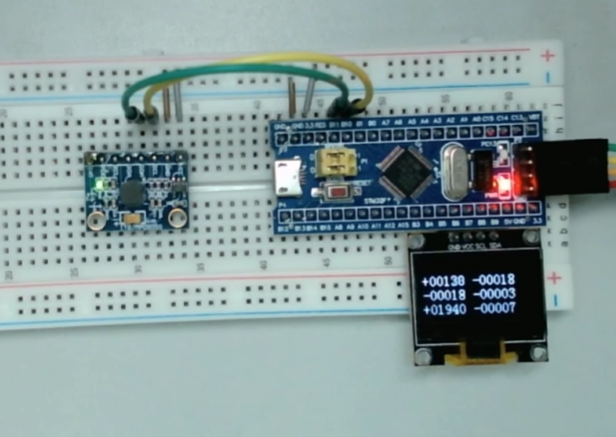
加速度计最大量程为16g

左侧为加速度计,右侧为角速度测量值


硬件IIC读写MPU6050

CR:控制寄存器

DR:数据寄存器

SR:状态寄存器

STM32IIC外设
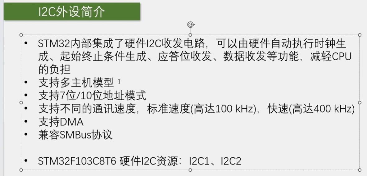
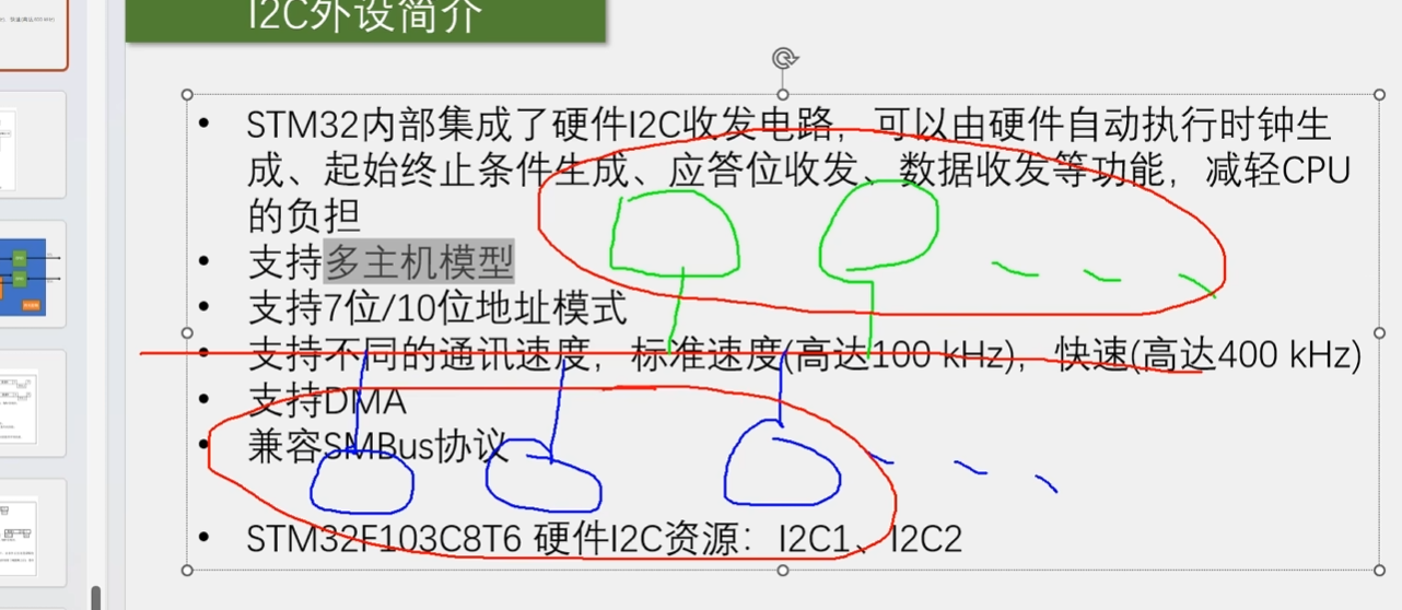
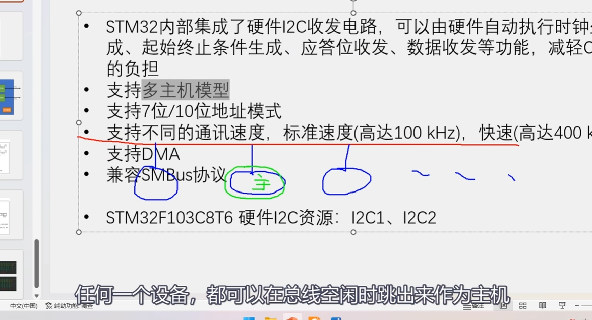
多主机模型

一主多从
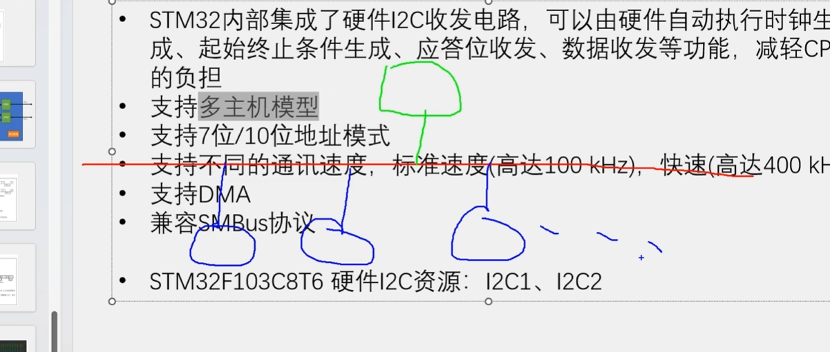
多主多从

固定多主机:
可变多主机:
GPIO复用输入和复用输出

IIC主机发送流程图

IIC主机接收流程图
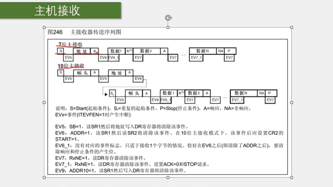
库函数解释

产生起始条件

void I2C_GenerateSTART(I2C_TypeDef* I2Cx, FunctionalState NewState);

生成终止条件

void I2C_GenerateSTOP(I2C_TypeDef* I2Cx, FunctionalState NewState);

配置在收到一个字节后,是否给从机应答

void I2C_AcknowledgeConfig(I2C_TypeDef* I2Cx, FunctionalState NewState);

写数据到数据寄存器DR

void I2C_SendData(I2C_TypeDef* I2Cx, uint8_t Data);

读取DR的数据,作为返回值

uint8_t I2C_ReceiveData(I2C_TypeDef* I2Cx);

发送7位地址

void I2C_Send7bitAddress(I2C_TypeDef* I2Cx, uint8_t Address, uint8_t I2C_Direction);

状态监控函数的官方说明

1
2
3
4
5
6
7
8
9
10
11
12
13
14
15
16
17
18
19
20
21
22
23
24
25
26
27
28
29
30
31
32
33
34
35
36
37
38
39
40
41
42
43
44
45
46
47
48
49
50
51
52
53
54
55
56
57
58
59
60
61
62
63
64
65
66
67
68
69
70
71
72
73
74
75
76
77
/**
* @brief
****************************************************************************************
*
* I2C State Monitoring Functions
*
****************************************************************************************
* This I2C driver provides three different ways for I2C state monitoring
* depending on the application requirements and constraints:
*
*
* 1) Basic state monitoring:
* Using I2C_CheckEvent() function:
* It compares the status registers (SR1 and SR2) content to a given event
* (can be the combination of one or more flags).
* It returns SUCCESS if the current status includes the given flags
* and returns ERROR if one or more flags are missing in the current status.
* - When to use:
* - This function is suitable for most applications as well as for startup
* activity since the events are fully described in the product reference manual
* (RM0008).
* - It is also suitable for users who need to define their own events.
* - Limitations:
* - If an error occurs (ie. error flags are set besides to the monitored flags),
* the I2C_CheckEvent() function may return SUCCESS despite the communication
* hold or corrupted real state.
* In this case, it is advised to use error interrupts to monitor the error
* events and handle them in the interrupt IRQ handler.
*
* @note
* For error management, it is advised to use the following functions:
* - I2C_ITConfig() to configure and enable the error interrupts (I2C_IT_ERR).
* - I2Cx_ER_IRQHandler() which is called when the error interrupt occurs.
* Where x is the peripheral instance (I2C1, I2C2 ...)
* - I2C_GetFlagStatus() or I2C_GetITStatus() to be called into I2Cx_ER_IRQHandler()
* in order to determine which error occurred.
* - I2C_ClearFlag() or I2C_ClearITPendingBit() and/or I2C_SoftwareResetCmd()
* and/or I2C_GenerateStop() in order to clear the error flag and source,
* and return to correct communication status.
*
*
* 2) Advanced state monitoring:
* Using the function I2C_GetLastEvent() which returns the image of both status
* registers in a single word (uint32_t) (Status Register 2 value is shifted left
* by 16 bits and concatenated to Status Register 1).
* - When to use:
* - This function is suitable for the same applications above but it allows to
* overcome the limitations of I2C_GetFlagStatus() function (see below).
* The returned value could be compared to events already defined in the
* library (stm32f10x_i2c.h) or to custom values defined by user.
* - This function is suitable when multiple flags are monitored at the same time.
* - At the opposite of I2C_CheckEvent() function, this function allows user to
* choose when an event is accepted (when all events flags are set and no
* other flags are set or just when the needed flags are set like
* I2C_CheckEvent() function).
* - Limitations:
* - User may need to define his own events.
* - Same remark concerning the error management is applicable for this
* function if user decides to check only regular communication flags (and
* ignores error flags).
*
*
* 3) Flag-based state monitoring:
* Using the function I2C_GetFlagStatus() which simply returns the status of
* one single flag (ie. I2C_FLAG_RXNE ...).
* - When to use:
* - This function could be used for specific applications or in debug phase.
* - It is suitable when only one flag checking is needed (most I2C events
* are monitored through multiple flags).
* - Limitations:
* - When calling this function, the Status register is accessed. Some flags are
* cleared when the status register is accessed. So checking the status
* of one Flag, may clear other ones.
* - Function may need to be called twice or more in order to monitor one
* single event.
*
*/

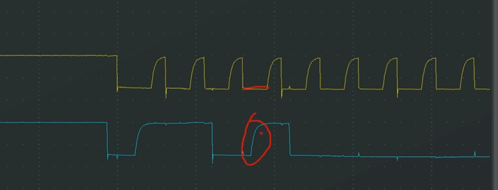
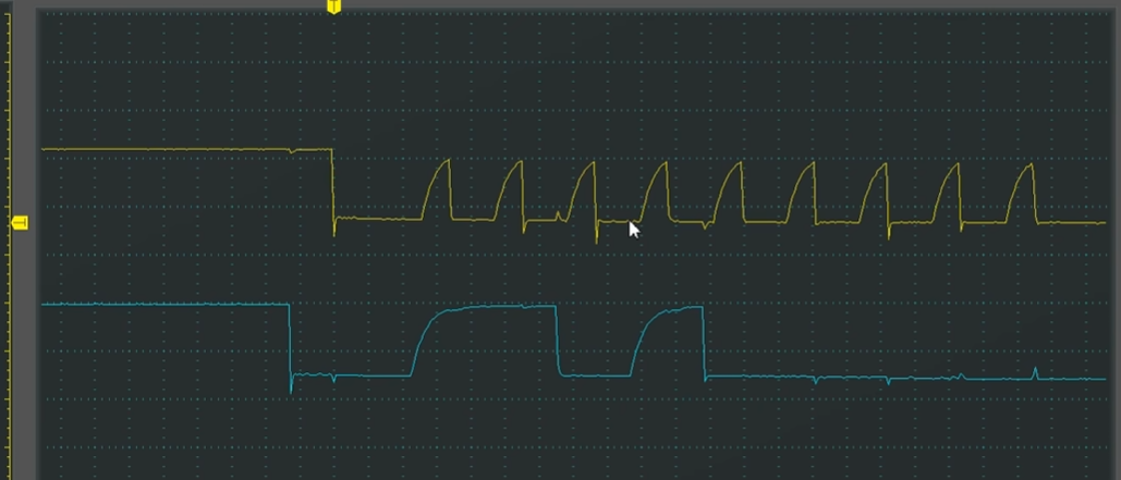
#IIC配置占空比的缘由

上升沿变化较慢,下降沿比较迅速,标准速度下,时钟占空比接近1:1,快速状态,占空比接近2:1

100KHZ
400KHZ
1
2
3
4
5
6
7
8
9
10
11
12
13
14
15
16
17
18
19
20
21
22
23
24
25
26
27
28
29
30
31
32
33
34
35
36
37
38
 *  1) Basic state monitoring
*******************************************************************************
*/

/**
* @brief Checks whether the last I2Cx Event is equal to the one passed
* as parameter.
* @param I2Cx: where x can be 1 or 2 to select the I2C peripheral.
* @param I2C_EVENT: specifies the event to be checked.
* This parameter can be one of the following values:
* @arg I2C_EVENT_SLAVE_TRANSMITTER_ADDRESS_MATCHED : EV1
* @arg I2C_EVENT_SLAVE_RECEIVER_ADDRESS_MATCHED : EV1
* @arg I2C_EVENT_SLAVE_TRANSMITTER_SECONDADDRESS_MATCHED : EV1
* @arg I2C_EVENT_SLAVE_RECEIVER_SECONDADDRESS_MATCHED : EV1
* @arg I2C_EVENT_SLAVE_GENERALCALLADDRESS_MATCHED : EV1
* @arg I2C_EVENT_SLAVE_BYTE_RECEIVED : EV2
* @arg (I2C_EVENT_SLAVE_BYTE_RECEIVED | I2C_FLAG_DUALF) : EV2
* @arg (I2C_EVENT_SLAVE_BYTE_RECEIVED | I2C_FLAG_GENCALL) : EV2
* @arg I2C_EVENT_SLAVE_BYTE_TRANSMITTED : EV3
* @arg (I2C_EVENT_SLAVE_BYTE_TRANSMITTED | I2C_FLAG_DUALF) : EV3
* @arg (I2C_EVENT_SLAVE_BYTE_TRANSMITTED | I2C_FLAG_GENCALL) : EV3
* @arg I2C_EVENT_SLAVE_ACK_FAILURE : EV3_2
* @arg I2C_EVENT_SLAVE_STOP_DETECTED : EV4
* @arg I2C_EVENT_MASTER_MODE_SELECT : EV5
* @arg I2C_EVENT_MASTER_TRANSMITTER_MODE_SELECTED : EV6
* @arg I2C_EVENT_MASTER_RECEIVER_MODE_SELECTED : EV6
* @arg I2C_EVENT_MASTER_BYTE_RECEIVED : EV7
* @arg I2C_EVENT_MASTER_BYTE_TRANSMITTING : EV8
* @arg I2C_EVENT_MASTER_BYTE_TRANSMITTED : EV8_2
* @arg I2C_EVENT_MASTER_MODE_ADDRESS10 : EV9
*
* @note: For detailed description of Events, please refer to section
* I2C_Events in stm32f10x_i2c.h file.
*
* @retval An ErrorStatus enumeration value:
* - SUCCESS: Last event is equal to the I2C_EVENT
* - ERROR: Last event is different from the I2C_EVENT
*/

解决WHILE死循环等待的问题

多个while,比较危险,一旦通信出现问题,程序直接卡死

1
2
3
4
5
6
7
8
9
10
11
12
13
14
15
16
17
18
19
20
21
22
23
24
25
26
27
28
29
void MPU6050_WriteReg(uint8_t RegAddress,uint8_t Data)
{
/*软件I2C,阻塞式程序
MyIIC_Start();
MyIIC_SendByte(MPU6050_ADDRESS);
MyIIC_ReceiveAck();//可以加判断,确保时序的正确
MyIIC_SendByte(RegAddress);//指定要写入的寄存器
MyIIC_ReceiveAck();
MyIIC_SendByte(Data);
MyIIC_ReceiveAck();
MyIIC_Stop();
*/
//硬件IIC,非阻塞式程序

I2C_GenerateSTART(I2C2,ENABLE);

while(I2C_CheckEvent(I2C2,I2C_EVENT_MASTER_MODE_SELECT ) !=SUCCESS);//事件监测

I2C_Send7bitAddress(I2C2,MPU6050_ADDRESS,I2C_Direction_Transmitter);//选择I2C外设,从机地址,从机地址最低位。此函数自带接收应答的功能
while(I2C_CheckEvent(I2C2,I2C_EVENT_MASTER_TRANSMITTER_MODE_SELECTED) !=SUCCESS);

I2C_SendData(I2C2,RegAddress);//写入DR,需要等待EV8事件
while(I2C_CheckEvent(I2C2,I2C_EVENT_MASTER_BYTE_TRANSMITTING) !=SUCCESS);

I2C_SendData(I2C2,Data);
while(I2C_CheckEvent(I2C2,I2C_EVENT_MASTER_BYTE_TRANSMITTED) !=SUCCESS);//发送完最后一个字节,需要监测EB8_1事件

I2C_GenerateSTOP(I2C2,ENABLE);
}

保护程序

1
2
3
4
5
6
7
8
9
10
11
12
13
void MPU6050_WaitEvent(I2C_TypeDef* I2Cx, uint32_t I2C_EVENT)
{
uint32_t Timeout;
Timeout= 10000;
while(I2C_CheckEvent(I2Cx,I2C_EVENT) != SUCCESS)
{
Timeout--;
if(Timeout==0)
{
break;
}
}
}

DMP库

digital motion processor数字运动处理器,mpu6050自带的一个硬件,可以直接输出用于姿态结算的四元数
卡尔曼滤波